Experimental apparatus:
the tandem-multipass Fabry-Perot interferometer
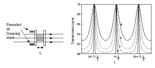
In a typical Brillouin scattering experiment one reveals acoustic or spin waves with frequencies in the range between about 1 and 150 GHz. In order to extract the weak inelastic component of light from the elastically scattered contribution, a high-resolution spectrometer is required. To this aim, the best combination of high resolution and good throughput is achieve using a Fabry-Perot interferometer (FPI)[i] as a scanning spectrometer. This system consists of two very flat mirrors mounted accurately parallel to each other with a variable spacing. For a fixed distance L1 the interference condition is such that only light of wavelength L1 will be transmitted, with L1=m L1/2 where m is an integer. Therefore, this instrument acts as a band-pass frequency filter whose peak transmission is close to unity over a narrow spectral interval, as shown in Fig.1.
Fig. 1
However, one has different
interference orders which are separated in frequency by c/2L1 Hz. This interorder spacing is called the free
spectral range (FSR). The width of the transmission peak determines the
resolution of the instrument. The ratio of the FSR to the width is known as the
finesse F, whose value depends on the
mirror reflectivity R, although
strumental aperture and mirror flatness are also important parameters. In
practice, the finesse is limited to values less than about 100 and this places
an upper limit on the possible contrast, where the contrast C
is the ratio of maximum to minimum transmission given by:[ii]
In
opaque materials, it is usual that the elastically scattered light exceeds the
intensity of the Brillouin component by more than a factor of 104-105,
so that the above contrast is not sufficient for measuring in such a situation.
A way for increasing the spectral contrast is the introduction of the multi-pass
operation: by sending back a few times the light through the same interferometer,
the contrast can be increased up to values close to 1010 and this is
sufficient for Brillouin scattering experiments in opaque materials.
In order to avoid the overlap of neighbouring interference order and extend the range of frequency investigated, it is possible to combine two interferometers of unequal mirror spacing (tandem operation), as shown in Fig. 2.
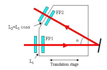
Fig. 2
The first
interferometer of spacing L1
transmits wavelengths
L1 = 2L1/m1
(2a)
for
integral m1, while the second interferometer of spacing L2
transmits wavelengths
for
integral m2.
Only
if L1 =
L2
light will be transmitted through the combination. It is important to notice,
however, that to scan the transmitted wavelength, it is necessary to increment
the mirror spacings L1 and L2
by DL1,
and DL2
such that:
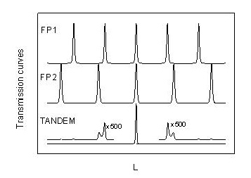
In the Sandercock interferometer this condition is achieved mounting the interferometers on the same scanning stage, one with the mirror axis parallel to the scan direction, the other off set by an angle a. It is clear that the spacings of the two interferometers satisfy the equation L2=L1cosa. The synchronization condition given by Eq. 3 is thus satisfied. In this way, it is possible to increase the FSR by a factor 10-20 over that of the single interferometer, although, as shown in Fig. 3, small ghosts remain of the suppressed orders.
The
real interferometer
Now we present a synthetic description of the real tandem-multipass interferometer introduced by J. R. Sandercock about twenty years ago, opening the way for direct observation of surface magnons in thin films. A detailed description of this instrument can be found in Ref. [iii] and [iv]. The principle of the construction of the interferometer is illustrated in Fig. 4.
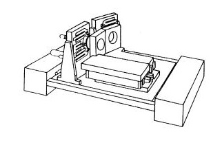
Fig. 4
A scanning stage consisting of a deformable parallelogram rides on top of a
roller translation stage. The former, actuated by a piezoelectric transducer,
provides completely tilt-free movement of the interferometer mirrors over scan
lengths up to 10 mm or more. The latter enables the mirror spacing to
be set to the desired value in the range 0-50 mm. A small parallel-plate
capacitor is then used to measure the scan displacement and this information is
used in a feedback loop in order to linearize the scan displacement with respect
to the applied scan voltage.
The
advantages of this construction system are summarized below:
(a)
completely tilt-free scan;
(b)
highly linear scan (less than 0.5 nm non-linearity over 5 mm
scan);
(c)
ability to change mirror spacing without losing alignment; and
(d)
stable against temperature change despite simple construction of aluminum and
cast iron.
In
order to avoid the noise caused by building vibrations, which typically have
their maximum amplitudes in the range 10-20 Hz, the complete optical system can
be isolated by a soft passive springs in the form of damped air columns. An
alternative and even better solution is to mount the optical table rigidly on
the floor, but to isolate the interferometer from the optical table by means of
a dynamic isolation systems, using feedback control[v].
Note that an enclosure is required around the interferometer to protect it from
sound waves which can excite high-frequency resonances in the system and to
reduce the influence of thermal fluctuations and dust.
It is important to recall here that for useful and easy operation of the
interferometer, a simple procedure for obtaining mirror alignment is needed.
This is achieved in Sandercock-type interferometers, by a motorized variation of
the position of a few optical components, which permits to operate in reflection
from the two Fabry-Pèrot cavities, instead of in the transmission mode.
Given
the low intensity of the Brillouin signals, single-photon counting is necessary
for the detection system. Low-noise photomultiplier tubes (PMT) having dark
counts not higher than 1-2 counts per second are generally used for this purpose.
A disadvantage of this type of detector is the low quantum efficiency of the
photocathode. Quite recently a new generation of low-background noise,
single-photon avalanche photodiodes with a quantum efficiency higher than a
typical PMT, have also been available. The electronics that follows is standard
when single- photon signals are passed to an amplifier, a pulse shaper, and then
counted and stored by an multichannel analyzer.
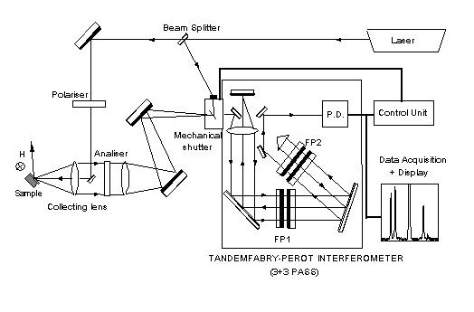
Fig. 5
Figure 5 shows a schematic diagram of the whole experimental apparatus
used for a BLS experiment in the backscattering configuration, which is usually
exploited in the case of experiments on thin films and layered structures. In
addition to the box containing the tandem-multipass interferometer and the
optical components necessary for the multipass operation (3+3 passes in our
case), one can see the external optics which is needed to focus the incident
laser beam onto the surface of the specimen. In usual experiments the specimen
is placed between the poles of an electromagnet with the external magnetic field
applied perpendicular to the scattering plane and parallel to the film surface.
In backscattering geometry the same lens (usually a commercial camera objective)
is used to focus light and to collect the back-scattered photons for analysis
through the interferometers. In this geometry, due to the conservation of the
wavevector component parallel to the film surface, the wavevector of magnons
revealed in the spectra is linked to the optical wavevector kI by the simple relation:
q|| =2
kI sin qi
(4)
where
qi
is
the angle of incidence of light. In order to reduce the noise level and to
suppress signals from acoustic phonons an analizer is put at the entrance of the
interferometer in order to stop scattered photons whose polarization is parallel
to that of incident photons.
[i] P. Jaquinot, Rep. Progr. Phys.
23, 268 (1960).
[ii] Born M. and E. Wolf, Principles
of optics , sixth edition (Pergamon, New York, 1984).
[iii] J.R. Sandercock, in Light
Scattering in Solids III, ed by M. Cardona and G. Güntherodt (Springer-Verlag,
Berlin, 1982), p.173.
[iv] F. Nizzoli and J.R.
Sandercock, in 'Dynamical Properties of Solids', vol. 6, ed. by G.K. Horton
and A.A. Maradudin (North Holland, Amsterdam, 1990) p.307.
[v] J.R. Sandercock, in Vibration
Control in Optics and Metrology, Soc. Photo-optical Instrumentation
Engineers, 732, 157 (1987).